Please follow the below steps to monitor memory usage in oc4j 10.1.3.x using JConsole.
Monitoring stand alone OC4J:
--------------------------------------------------------------------------------
1.Install JDK 1.5 first or if you have JDK 1.5 installed , you can find JDK in $JAVA_HOME/bin/ directory.
2.Set the java option -Dcom.sun.management.jmxremote
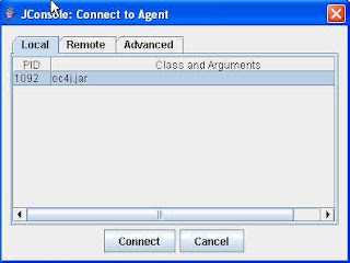
3.Start the JConsole JMX client (./jconsole) and then it will display the local oc4j instance as below
4.Click on Connect
Once connected , Click the Memory tab.
Monday, April 26, 2010
How to change Weblogic Default password?
Please follow the below steps to change the Weblogic login id or password from previous value to something else:
1).Move inside your Domain Directory.
Example: (here WLST_Domain is my Domain Name)
C:\bea\user_projects\domains\WLST_Domain
2). move inside the Servers directory
Example:
C:\bea\user_projects\domains\WLST_Domain\servers
3). Move inside the Admin Server Directory...In my case the Administration Server name is "AdminServer"
Example:
C:\bea\user_projects\domains\WLST_Domain\servers\AdminServer
4). Take a Backup of "data" folder, Means Just rename "data" directory to some other Directory like "data_OLD"
5). Inside AdminServer Create a directory with name "security"
C:\bea\user_projects\domains\WLST_Domain\servers\AdminServer\security
6). Inside the "security" directory Just create a file with the name "boot.properties"
7). Inside the boot.properties file Just enter the UserName and Password in two lines
Example: below is the content of "boot.properties"...only following two lines
username=weblogic
password=weblogic
8) Start the WebLogic Server
Note: If you are using WebLogic 10.3.1 then the default password may be either "weblogic1" or "welcome1"
Friday, April 23, 2010
What is the difference between Orchestration and choreography?
Orchestration versus Choreography
Web services usually expose operations of certain applications or information systems. Consequently, combining several Web services actually involves the integration of the underlying applications and their functionalities.
Web services can be combined in two ways:
* Orchestration
* Choreography
In orchestration, which is usually used in private business processes, a central process (which can be another Web service) takes control of the involved Web services and coordinates the execution of different operations on the Web services involved in the operation. The involved Web services do not "know" (and do not need to know) that they are involved in a composition process and that they are taking part in a higher-level business process. Only the central coordinator of the orchestration is aware of this goal, so the orchestration is centralized with explicit definitions of operations and the order of invocation of Web services.
Choreography, in contrast, does not rely on a central coordinator. Rather, each Web service involved in the choreography knows exactly when to execute its operations and with whom to interact. Choreography is a collaborative effort focusing on the exchange of messages in public business processes. All participants in the choreography need to be aware of the business process, operations to execute, messages to exchange, and the timing of message exchanges.
From the perspective of composing Web services to execute business processes, orchestration is a more flexible paradigm and has the following advantages over choreography:
* The coordination of component processes is centrally managed by a known coordinator.
* Web services can be incorporated without their being aware that they are taking part in a larger business process.
* Alternative scenarios can be put in place in case faults occur.
Specifying Physical and Logical Directory paths while using File Adapter.
Inbound / Outbound directory names while configuring read /write operation in File Adapter can be specified in either way:Physical Directory Path / Logical Directory Path
Physical paths are values such as c:\inputDir
Logical properties are specified in the inbound/outbound WSDL file and their logical-physical mapping is resolved using partner link properties. You specify the logical parameters once at design time, and you can later modify the physical directory name as needed.
Provide a logical name. For example, the generated inbound WSDL file looks as follows for the logical input directory name InputFileDir.
LogicalDirectory="InputFileDir"
In the BPEL partner link of the bpel.xml file, you then provide the physical parameter values (in this case, the directory path) of the corresponding logical ActivationSpec or InteractionSpec. This resolves the mapping between the logical directory name and actual physical directory name.
C:/deepak/InputDir/
Physical paths are values such as c:\inputDir
Logical properties are specified in the inbound/outbound WSDL file and their logical-physical mapping is resolved using partner link properties. You specify the logical parameters once at design time, and you can later modify the physical directory name as needed.
Provide a logical name. For example, the generated inbound WSDL file looks as follows for the logical input directory name InputFileDir.
LogicalDirectory="InputFileDir"
In the BPEL partner link of the bpel.xml file, you then provide the physical parameter values (in this case, the directory path) of the corresponding logical ActivationSpec or InteractionSpec. This resolves the mapping between the logical directory name and actual physical directory name.
What is EAI , purpose of EAI and EAI Patterns?
Enterprise Application Integration (EAI) is defined as the use of software and computer systems architectural principles to integrate a set of enterprise computer applications.
Purposes of EAI:
EAI can be used for different purposes:
* Data (information) Integration: Ensuring that information in multiple systems is kept consistent. This is also known as EII (Enterprise Information Integration).
* Vendor independence: Extracting business policies or rules from applications and implementing them in the EAI system, so that even if one of the business applications is replaced with a different vendor's application, the business rules do not have to be re-implemented.
* Common Facade: An EAI system could front-end a cluster of applications, providing a single consistent access interface to these applications and shielding users from having to learn to interact with different software packages.
Integration patterns
There are two patterns that EAI systems implement:
Mediation:
Here, the EAI system acts as the go-between or broker between (interface or communicating) multiple applications. Whenever an interesting event occurs in an application (e. g., new information created, new transaction completed, etc.) an integration module in the EAI system is notified. The module then propagates the changes to other relevant applications.
Federation:
In this case, the EAI system acts as the overarching facade across multiple applications. All from the 'outside world' to any of the applications are front-ended by the EAI system. The EAI system is configured to expose only the relevant information and interfaces of the underlying applications to the outside world, and performs all interactions with the underlying applications on behalf of the requester.
Both patterns are often used concurrently. The same EAI system could be keeping multiple applications in sync (mediation), while servicing requests from external users against these applications (federation).
Access patterns
EAI supports both asynchronous and synchronous accesss patterns, the former being typical in the mediation case and the latter in the federation case.
Lifetime patterns
An integration operation could be short-lived (e. g., keeping data in sync across two applications could be completed within a second) or long-lived (e. g., one of the steps could involve the EAI system interacting with a human work flow application for approval of a loan that takes hours or days to complete).
Thursday, April 22, 2010
How to configure EMS FT as well as LB in BW processes?
In EMS connection , specify the FT URL(tcp://host:7444,tcp://host:7555)
In the EAR , create 2 process archives.
Create 2 FT groups.
During deployment,target 2 process engines to each FT group.
Now there will be 4 PE in total , out of which 2 will be active at any time.
The active PEs will run in load balanced mode.
In the EAR , create 2 process archives.
Create 2 FT groups.
During deployment,target 2 process engines to each FT group.
Now there will be 4 PE in total , out of which 2 will be active at any time.
The active PEs will run in load balanced mode.
How to onfigure BW to communicate with JBOSS JMS?
Please follow the below steps to configure BW to connect to JBOSS JMS:
1.Add jbossall-client.jar in designer std classpath or put this jar file in tpcl/tpcl_ver/lib folder.
2.In JMS connection’s configuration tab check ‘Use JNDI for Connection Factory’
Set the following fields as specified:
JNDI Context Factory: org.jnp.interfaces.NamingContextFactory
JNDI Context Url : jnp://jboss_server_url:jboss_port
In advanced tab , set these values:
Topic ConnectionFactory : java:/ConnectionFactory
Queue ConnectionFactory : java:/ConnectionFactory
Test the connection from Designer
How to use JProbe for profiling TIBCO BW process?
Use the below values from bwengine.tra file to set JProbe(a J2SE application) parameters to start profiling TIBCO BW appliation.
JProbe Parameter bwengine.tra vaue
===========================================================================
Main Class com.tibco.pe.PEMain (java.start.class in bwengine.tra)
Argument Directoy location of BW project
Classpath add all the jar files needed by BW here
JVM\bin\java.exe
Start the JProbe and you can see the profiling information now.
JProbe Parameter bwengine.tra vaue
===========================================================================
Main Class com.tibco.pe.PEMain (java.start.class in bwengine.tra)
Argument Directoy location of BW project
Classpath add all the jar files needed by BW here
JVM
Start the JProbe and you can see the profiling information now.
Sending Hawk Alerts from BW process
It is not possible to send Hawk Alerts from TIBCO BW process.
Hawk alerts can only be generated using Hawk Rulebase.
Even using Hawk API in BW will not help.
This can be achieved using below methods , but Hawk rulebase will be required anyways:
1. Write a given pattern to some log file; then use Logfile microagent to monitor the pattern and send an alert.
2. Send a given RV message; then use Messaging microagent to receive it and send an alert.
Subscribe to:
Posts (Atom)